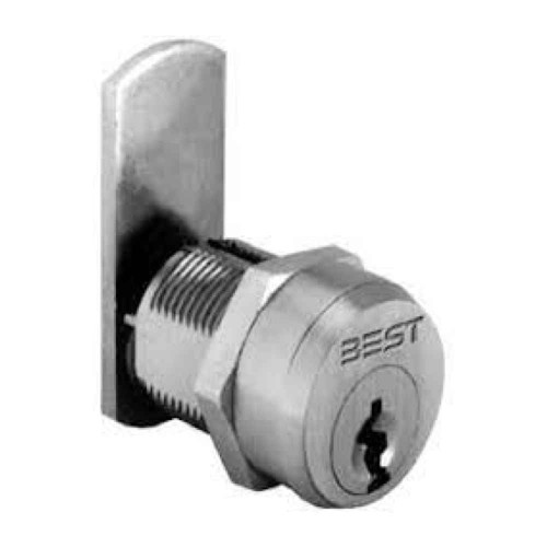
BEST 5E SERIES CAMS OVERVIEW
The 5E utility cylinder lock fits standard 3/4" diameter cylinder installations such as wood or metal desks, file cabinets, vending machines, utility and storage cabinets, elevators and security alarm control panels. The complete 5E assembly includes a combinated 3/4" cylinder with cam, hex nut, lock washer and spacer collar.
FEATURES
- Maximum mounting surface thickness – 5E utility cylinder locks may be mounted on surfaces with the following maximum thickness: 5E6: 11/16", 5E7: 27/32"
- Keying – May be keyed individually, keyed alike or masterkeyed into a new or existing Best standard masterkeyed security system.
- Service – 5E cylinders may be recombinated and serviced onsite. Special service equipment is available (see Service Equipment Section of Best catalog).
- Finish – 626 satin chrome only.
A – Cam Motion and Degree of Rotation
When ordering 5E cylinders, specify the cam motion type and degree of rotation. Available cam motion types are listed below. Different type motions are limited to different degrees of key rotations.
- Type A – Direct motion - Key and cam rotation is direct. Key may be removed in locked position only. Motion is 360 degrees right or left.
- Type B – Limited motion - Key and cam rotation is direct. Key may be removed in locked position only. Motion is limited to 90 degrees or 180 degrees right or left.
- Type C – Lost motion. Cam rotates 90 degrees right or left. Key rotates 360 degrees. Key removal with cam in locked or unlocked position.
- Type D – Throw member drive - Key and drive motion is direct. Key may be removed in locked position only. Motion is 360 degrees right or left.
B – Determine Ring Length
A spacer collar may be required to position the cam for proper lock operation. The spacer collar is installed between the 5E cylinder head and the mounting surface. To determine the proper length of the spacer collar, add together: the desired distance from the cam to the inside of the mounting surface (“A” above) to the measured thickness of the mounting surface (“B” above). Then, subtract this total from: 31⁄32” when installing a 5E6, or 1 1⁄8” when installing a 5E7. The remainder is the collar length, which is illustrated.
C – Select Proper Cam Type
Cam
Cams for 5E cylinders are available with a number of variations to suit the particular application as required. Two major variations that must be designated on the order are: A.) The cam type, and B.) The cam length.
Cam Types
The following cam types are available for the Best 5E cylinder. Other designs are available upon request.
Cam Types
C1– Straight cam mounted for fixed motion operation (used in conjunction with type “A” and type “B” motions). To order cam separately, designate 5E-C1 and length from code chart at option D.
C3– Straight cam mounted for lost motion operation (used in conjunction with type “C” cam motions). To order cam separately, designate 5E-C3 and length from code chart at option D.
2A– Offset cam (inward mount) for lost motion operation (used in conjunction with type “A” and type “B” motions). To order cam separately, designate 5E-C2A and length from code chart at option D.
2B– Offset cam (outward mount) for fixed motion operation (used in conjunction with type “A” and type “B” motions). To order cam separately, designate 5E-C2B and length from code chart at option D.
4A– Offset cam (inward mount) for lost motion operation (used in conjunction with type “C” cam motions). To order cam separately, designate 5E-C4A and length from code chart at option D.
4B– Offset cam (outward mount) for lost motion operation (used in conjunction with type “C” cam motions). To order cam separately, designate 5E-C4B and length from code chart at option D.
D– Direct throw member drive and tailpiece. Throw pins engage cylinder to flat spindle tailpiece. The standard flat spindle tailpiece is 11/16" and may be cut to length desired. To order spindle separately, designate 5E-D.
D – Determine Cam Length
Cam length is determined by measuring from center of the cam rotation to the tip of the cam.
E – Cam Mounting Position and Cam Direction
Direct Throw Member Drive and Tailpiece Cams may be mounted in one of four “clock” positions as pictured below. Designate cam mounting and rotation direction (right-“R” left-“L”). Key is only removable in the locked position, unless ordering type C. (Available in locked and unlocked positions.).
RESOURCES & DOWNLOADS
Manufacturer Resources
Product Specs
- Series:
- 5E Series
- Subcategory:
- Parts and Accessories
- Product Group:
- Parts and Accessories
- Product Subgroup:
- Parts and Accessories
- Product Type:
- Cams
- Commercial/Residential:
- Residential
- Collection:
- E Series Cylinders
- Parts and Accessories Type:
- Replacement Parts
- Product Attribute:
- Parts and Accessories
- Product Category:
- Mechanical Locks
- Department:
- Door Hardware


